Hello Lightning Tamers!
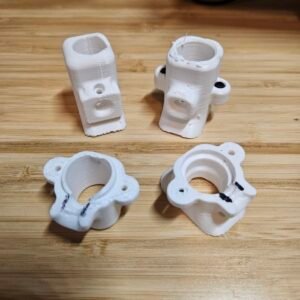
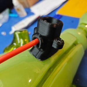
This is a look behind the scenes at version 2 of the 3D printed electrode protectors I’ve been developing for the Atupa Series. It’s already made it into three pieces currently in progress — Sour Mint, Hyacinth Galaxy, and Cobalt Shock — so this isn’t just theory anymore, it’s a test put into action with intention.
The protector is designed to do a few things at once:
- Protect the electrode and tubulation from damage — bumps, rolling, general handling.
- Cinch and hold the HV wire in place, acting as a strain relief mechanism.
- Provide a cavity that gets filled with a low-viscosity dielectric silicone once everything’s seated.
About the silicone: with the Cobalt Spark, I used electronic potting resin (same as used in the Dyna-Meter Probe) to seal electrode wire from air. This time I wanted something softer — something that could flex and absorb strain when force gets applied to the protector instead of transferring all of it straight to the electrode.
I’m currently testing Langxist Silicone Conformal Coating for this. I want to be clear that I’m not calling this the answer — it’s a test. But it’s affordable, and it covers a small cavity without trapping air bubbles, which fits the criteria.
It would also be important to note that the way the 3D print gets adhered — PC-7 epoxy — already makes repair difficult. There are workable methods to remove it with heat and elbow grease, but it’s not fun. And soda-lime glass is inherently less forgiving to repair than borosilicate, so if a piece fails at the electrode — and the tip-off, where the gas is sealed ( most vulnerable point on the whole sculpture) — there’s a real chance you have to accept impermanence rather than fix it.
When assembling the electrical system, I follow similar logic I used on the Trophy Moose collaboration with Chris Ahalt:
- Electrical interface / electrode
- Non-conductive shell / 3D printed material
- HV wire — 40kV DC
- Strain relief to prevent the wire from pulling out of the electrode or shifting position
- Dielectric seal / electronics silicone
Mounting Hardware
In earlier pieces — Cobalt Spark and Neon Citrus — I combined the mounting hardware and the electrical connections in the same spot. That simplified the piece and kept the hardware’s visual presence to a minimum, letting the electrode shielding double as the mount.
As I keep pushing the color layering in my work, I keep running into the same constraint — one I’ve gotten a lot better at managing compared to 10 years ago: to get a piece that can be engraved, you need a layer of clear glass between the color layers, and best practice is a minimum of 1/2″ to 3/4″ thick. That adds up fast, making the finished work considerably heavier than something like Cobalt Spark — where haste and miscalculation on my part led to thinner, lighter pieces that left little margin for error when engraving, the same issue I ran into with some of the other pieces I made during my Corning residency in 2024.
So I’ve been working on mounting these pieces from the bottom — same PC-7 epoxy, but this time using PC-Blend filament, a much stronger 3D print material, since it’s now doing structural work instead of just protective work. The idea is a mounting solution, while the electrode comes out the back of the piece, keeping the front clean. In future works I’m looking to allow for artwork being viewed in round, and that presents new design challenges that change the process of my work.
Tool Talk: I picked up a Prusa Core ONE+ v1 this year, which was a massive upgrade to my printing capability. My old Ender 3 — “Theseus’ printer” at this point, since it’s been rebuilt piece by piece over 6 years — finally got retired. (I’m planning to convert it into a small laser cutter/engraver at some point, which honestly sounds like a fun winter project TBD)
Return to Electrodeless
Long term, I want to return to electrodeless pieces so I can start exploring gas mixtures I can’t currently use with confidence in a standard electrode setup — iodine and oxygen being the big ones I’m after.
Electrodeless — or capacitive — pieces are actually foundational to early and modern plasma globes. Using a capacitive interface to transmit RF into the globe lets you work with reactive gases and elements with little to no loss or change in effects. The electrodes that got “adapted” into modern plasma work were really designed with neon signage in mind, as I noted in the blog, Borosilicate Electrodes Restocked, and the Sunsetting of Yanlux.
Very few people have explored electrodes built specifically for plasma sculpture — and that’s work that takes just as much time and skill to develop as electrodeless does. I plan on learning and developing that too, alongside the electrodeless work. The work is never-ending.
The hardest part with electrodeless is the plasma driver side: building a capacitive interface that’s actually robust. That means thinking through:
- Layering conductive material, insulation, and adhesion in a way that prevents, Corona discharge, the ionization of the surrounding air at the contact point.
- Minimizing RF loss/energy loss by having the minimal distance between the vessel and the plasma driver.
- Deciding where the tubulation lives — as this is going to be hard to hide and protect
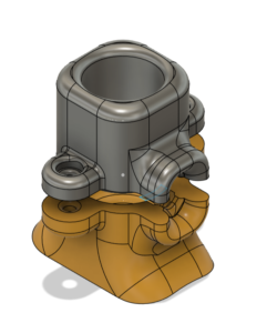
Right now this is still just a sketch, but here’s how I actually work through a problem like this:
- I start from things I’ve taken apart or used before
- Then go find references to understand
- Replicate what’s happening inside them.
- Then proceed to build iteratively in CAD
- Print and Repeat.
For this specific design, the starting point was something as simple (as complex) as a button — the kind that in most devices relies on a spring for contact pressure. I’m trying to get the geometry of the housing itself to do that job instead: keep the contact point contained, maintain consistent pressure, and prevent it from working loose, sticking, or falling out entirely.

Right now it’s just a drawing, but I already know the constraints going in — this is HV AC, so the components can’t arc in open air, and I need to keep any added lead length to an absolute minimum. On top of that, the design has to build in real protective measures against burns, fire, and shock.
This one’s going to be trial and error with research woven through it, and I’m aware of my own tendencies toward upgrade creep — finding something that can be changed over time to improve an older setup before a full revision is applied to newer work.
Speaking of revisions in progress: the next update picks back up with VIGIL, continuing where Dev Log #1 — Building VIGIL, Part 1: PVM10 Mounting Design left off. More on that soon.
The goal this year is to finish these work and not linger too long on the hardware.